Self-propelled hydraulic inverting bridge formwork construction steps

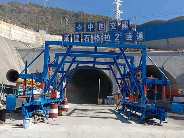
The self-propelled hydraulic inverting bridge formwork adopts mechatronics and hydraulic integration design, equipped with multi-functional automatic walking device, front support, rear lateral movement mechanism, hydraulic self-balancing system, which can realize automatic vertical movement, rise and fall, and automatic horizontal movement, with a high degree of automation , Can adapt to a variety of construction work environment.

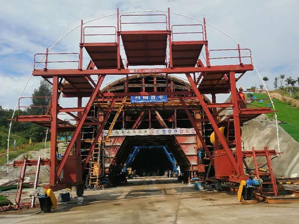
The self-propelled hydraulic inverting bridge formwork is composed of the main body of the trestle bridge, hydraulic system, electrical control system, and walking system.

The main structure of the main bridge: 8 40b# I-beams are arranged in parallel along the longitudinal direction of the tunnel at the bottom of the bridge, 4 20# channel steels and 6 20b# I-beams are arranged horizontally along the tunnel on the bottom of the bridge, with box-shaped structures on both sides and the middle 25# I-shaped steel support connection. The hydraulic system includes various lifting cylinders and related hydraulic pump stations and pipelines; the electrical system is responsible for controlling the operation of each system, mainly composed of various relays, switches, circuit breakers, etc.

The traveling system is composed of a motor reducer, a transmission chain, a box body, a traveling wheel, etc. There are 4 groups, which are respectively placed on both sides of the end of the trestle body to realize the automatic walking of the trestle body. The walking device can realize horizontal and vertical walking, which is flexible and convenient.

Hydraulic inverting bridge formwork walking principle

In order to meet the requirements of movement, a mobile walking mechanism is set at both ends of the trestle bridge, and a limit warning device is set; when walking, the lifting and lowering of the slope bridge at both ends of the trestle bridge is completed by the hydraulic system actuator. The self-propelled hydraulic inverting bridge formwork is mainly composed of the main bridge, traveling device, hydraulic system, electrical system, limit device and alarm system. The trestle bridge is moved. When moving, it is driven by a motor and driven by a gear pinion to drive the walking wheel to move on the walking track. The working steps are as follows:

Hydraulic inverting bridge formwork

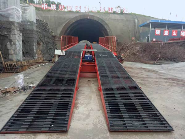
Start the main bridge lifting cylinder installed at the end of the trestle bridge to make the trestle bridge slope off the ground, and then with the cooperation of workers, drag the trestle bridge walking track forward. After the track is dragged to the end, shrink the main bridge lifting cylinder to start the traveling motor. The trestle moves forward on the track, after moving to the end of the track, repeat the above steps until the trestle is in place (the trestle’s lateral movement is the same as this). After the trestle bridge is in place, the main bridge lifting cylinder is lifted up, so that the running wheels are not stressed. After being fixed, the front and rear slope bridges are put down.

Hydraulic inverting bridge formwork construction technology

According to the requirements of the construction schedule, the construction of the tunnel entering the invert position, in order to ensure that the invert construction continues and the slag from the tunnel excavation and the transportation of materials in the tunnel are not affected by the invert excavation, so the invert excavation slot is installed the trestle bridge will be constructed. After the strength of the poured invert concrete meets the traffic strength requirements, the trestle bridge can be pushed forward to the excavation groove at the bottom of the next tunnel, and then recycled. So as to realize the rapid and safe progress of tunnel construction.

Trestle installation and positioning

Plan ahead of time the personnel, materials and machinery required for processing. The installation of the trestle is carried out by professional and technical personnel. When the hydraulic inverting bridge formwork is erected, the bottom slag of the front platform of the trestle must be removed before the trestle is advanced, and the foundation must have a certain bearing capacity. The back end is laid on the top surface of the filling; the front ramp of the trestle bridge should be firmly connected with the trestle platform to ensure the safety of erection. After the trestle bridge is erected and installed in place, safety nets must be hung outside the guardrails on both sides of the trestle bridge to prevent the falling of gravel from hurting the operators of the inverted arch construction below; obvious slow-moving warning signs should be set at the front and rear of the trestle bridge, and the trestle bridge surface should have anti-skid measures.

Wheeled Hydraulic inverting bridge formwork

Trestle inspection

Before the trestle bridge is moved, erected and installed, the welding parts of the trestle bridge shall not have the phenomenon of welding seam falling off or welding seam cracking, and the supporting system shall be inspected to check whether the main beam and auxiliary components of the trestle bridge are cracked and deformed. If problems are found, the trestle shall not be carried out. Moving and erecting, the trestle can be moved and erected only after the processing is completed and the inspection is qualified.

Trestle move

Use an excavator or loader to set it in place, and walk on its own after it is in place: the inverted arch can only be moved after the strength of the filled concrete reaches the design requirements and the necessary protective measures must be taken. The movement must be slow to avoid damage to the quality of the finished concrete: trestle bridge When moving, full-time personnel must be assigned to uniformly command, and no one is allowed to stand in the trestle work area.

Invert excavation

(1) The invert excavation is divided into left and right parts, and half of the excavation is carried out first.

(2) In the first cycle, first excavate the left or right inverted arch, and park the trestle on the side where there is no excavation: park the slag truck on the trestle, and excavate the excavator on the surface to be excavated When excavating from the front to the rear of the trestle bridge, the excavator has been parked on the elevation surface of the inverted arch, so as to ensure that the excavator can load the slag into the slag truck.

(3) After excavating one side, operate the trestle bridge to move the trestle bridge to the side that has been excavated, and also park the slag truck on the trestle bridge, and the excavator will excavate on the surface to be excavated. When excavating from the front end to the back end of the trestle bridge, the excavator has been stopped on the elevation surface of the invert, so as to ensure that the excavator can load the slag into the slag truck; at this time, the invert excavation and the invert lining can be carried out simultaneously.

(4) Repeat the above process to complete the next cycle of invert construction.

Advantages of hydraulic trestle

(1) Through the application of the trestle bridge in the tunnel, the materials and tools for the construction of the tunnel face can pass from the upper part of the trestle bridge, reducing the interference between excavation construction and invert construction: at the same time, the trestle bridge has a large span and is an inverted arch The construction provides a streamlined work surface: the trestle itself is convenient and quick to install, walks more flexible, and has a high level of mechanization. These are conducive to speeding up the tunnel construction speed and solving the schedule problem, especially for the long tunnel and the tight construction period, the benefit of ensuring the schedule is very obvious.

(2) Compared with the simple trestle bridge, the use of movable hydraulic inverting bridge formwork, although the cost of manufacturing or purchase increases, but because it provides enough space for inverting operations, it can effectively organize flow construction. Improve production efficiency and speed up, especially in the case of long tunnels, which will play a role in reducing engineering costs.

(3) Ensure the safety of construction workers under the trestle bridge. The hydraulic inverting bridge formwork made of section steel is stable in structure, safe and reliable; the mobile trestle reduces the interference between working procedures, and the structural safety is improved compared with the simple trestle.

(4) It is beneficial to ensure the quality of tunnel construction. Due to the use of the trestle bridge, it is guaranteed that the invert is poured in one time, which is beneficial to ensure the quality of the invert.

Wheeled Hydraulic inverting bridge formwork

Precautions when using self-propelled hydraulic inverting bridge formwork

(1) Personnel operating the trestle bridge must be trained and qualified before they can carry out operations.

(2) When the hydraulic inverting bridge formwork is in place, pay attention to the flatness of the installation and the width of the installation to meet the design requirements to ensure the safety of the vehicle and the normal passage of vehicles with different wheel bases.

(3) The speed limit for vehicles passing through the trestle bridge should be determined according to the actual situation on site to ensure the stability and safety of the hydraulic inverting bridge formwork during work: construction personnel are prohibited from passing vehicles when working under the trestle bridge to ensure the safety of operators.

(4) Lay safety nets on the outside of the trusses on both sides of the trestle bridge to prevent the falling of gravel from hurting the construction operators below. The concrete and debris on the self-propelled hydraulic inverting bridge formwork should be cleaned up in time to keep the upper part of the trestle clean.

Concluding remarks

The application of hydraulic trestle has changed the existing tunnel invert construction organization mode. Under the premise of not affecting the tunnel face construction, the tunnel invert excavation, reinforcement binding, invert pouring and other operations are carried out at the same time to realize the excavation and invert the parallel operation of arch construction greatly saves construction time and improves the overall efficiency of tunnel construction.

Due to the automatic walking device, the trouble of manually moving the trestle bridge is reduced, the automation level of tunnel construction is improved, and the safety is enhanced. Become the technical basis for ensuring the quality, schedule, and cost control of the tunnel invert construction, and the technical basis for realizing the standardization of tunnel construction and the construction of humanized and civilized construction sites.

What are the key points for tunnel lining quality control?

Tunnel lining plays an important role in the support of tunnel engineering. It is to prevent deformation or collapse of surrounding rock. The permanent support structure built along the periphery of the tunnel body requires quality control of four major links in actual construction. Look down.

1. Construction of tunnel lining

(1) The secondary lining must be carried out when the deformation of the surrounding rock and the initial support is basically stable, and the displacement convergence speed is obviously slowing down, and the various displacements must reach 80% to 90% of the estimated total displacement.

(2) Before the construction of the lining, the waist line must be measured to control the deviation of the invert and foundation pouring, and the lining section base surface and vault elevation should be detected. The thickness error of the tunnel lining meets the design requirements to ensure the clearance height in the tunnel.

(3) The thickness and compactness of the lining must be checked after the construction of the lining, and the electrical signal of the corresponding frequency is generated by the transmitter according to the command of the control unit for detection.

(4) The construction site of the lining must be continuously measured, and continuously collected along the measuring line during the inspection, paying attention to stable movement and uniform speed.

The tunnel concrete maintenance formwork

2. Construction of tunnel lining structure

(1) Strictly control the mixing ratio of concrete, check the quality of raw materials before mixing, and do not change at will after verification by tests. Add accelerator according to the construction environment temperature.

(2) In order to ensure the quality of concrete, it must be sprayed and sprayed continuously; check whether the mechanical equipment is operating normally before construction.

(3) The steel mesh for lining must be spot welded into blocks at the intersection, and the anchor rods must be laid after completion to ensure that the mesh is close to the initial spray surface. After the construction is completed, the thickness of the concrete protective layer and the connection performance of the steel must be tested.

3. Tunnel lining template construction

(1) Ensure that the formwork engineering support is firm and stable, and detect whether there is excessive deformation and subsidence; the rigidity of the formwork support at the large variable section must be checked, and the setting must be correct before installation.

(2) Ensure that the surface of the formwork is cleaned, and the mold release agent is applied to ensure the quality of the concrete molding; during the construction, pay attention to the joints are flat and tight, and there is no hidden danger of dislocation.

(3) The error of each part of the control structure meets the requirements, the elevation of the vault does not exceed 10mm, the error of the center line does not exceed 10mm, and the error of clearance does not exceed 10mm.

Tunnel waterproof board laying formwork

4. Treatment of lining cracks

(1) The fine cracks can be painted with epoxy resin slurry after cleaning, and then the surface of the concrete can be treated with scraping material and toning material to achieve a beautiful effect.

(2) For penetrating cracks, V-shaped grooves must be cut along the direction of the cracks, and holes shall be drilled across the cracks in the grooves. After removing the debris, the epoxy cement mortar shall be used to anchor, and the same strength grade cement shall be used to smooth it.

(3) Dense cracks must be additionally waterproofed and reinforced. Cement mortar shall be injected into the cracks to ensure full grouting; anchor pads shall be installed 1 day after grouting, and then filled with epoxy mortar.

In summary, there are four points about the quality control of tunnel lining during the construction process. Only by doing these can the quality and safety of the tunnel be guaranteed.

More tunnel lining related articles:

WHAT ARE THE FACTORS AFFECTING THE TUNNEL LINING CONCRETE?

CAUSES AND TREATMENT OF CRACKS IN TUNNEL LINING

ANALYSIS OF KEY POINTS OF TUNNEL LINING CONSTRUCTION IN TUNNEL ENGINEERING

What are the factors affecting the tunnel lining concrete?

Introduction

As the development of road traffic brings rapid economic development, the construction of roads and tunnels is becoming more and more common. Under normal circumstances, during the tunnel lining construction, concrete often has problems and defects such as leaking bars, pitting and cracks. Although it has no direct impact on the actual use of the structure and the internal quality, due to its relatively high probability of occurrence, the lining The aesthetic appearance is affected to a certain extent, and the overall quality of the lining is reduced.

The factors affecting the tunnel lining concrete

The tunnel concrete maintenance formwork

(1) Freeze-thaw damage of concrete

Concrete has certain pores and expands after freezing. When the water retention of the concrete is high and the volume in the pores is small, the problem of excessive pressure will occur, and during the freezing and thawing process, the moisture on the surface of the concrete will be affected by the osmotic pressure, resulting in damage to the concrete.

(2) Constituent materials of concrete

In the process of on-site concrete mixing, the use of different materials directly affects the durability of the concrete. In some specific processes, the diameter of the cement particles will become thinner and thinner. Under such conditions, high heat of hydration will be generated. At the same time, the problems of high temperature difference and high shrinkage rate, concrete collapse is increasing, and the particle size of the aggregate is reduced to increase its workability. The addition of cement and admixtures also exacerbates the problem of heat of hydration, which directly leads to more serious problems of shrinkage and deformation of concrete.

(3) Rebar corrosion

If the concrete is in a highly alkaline environment for a long time, the surface of the steel will be oxidized to form a passivation film, which will not be damaged by rust. If the protective layer of concrete reinforcement is carbonized, it will cause a decrease in alkalinity, resulting in some air and moisture inside the concrete, which will lead to corrosion of the reinforcement.

Defect analysis of tunnel lining concrete

The defects of tunnel lining concrete construction mainly include leaking bars, pitted surfaces, holes, etc., and the solutions to these defects. For details, please see “TREATMENT AND PREVENTION OF TUNNEL LINING CONCRETE DEFECTS

Treatment measures for defects in tunnel lining concrete

Tunnel waterproof board laying formwork

(1) Conduct a detailed site survey

In order to make the tunnel construction proceed more smoothly, and to further ensure that the repaired concrete pavement is stronger, it is necessary to carry out certain surveys on the local construction road sections and determine the construction plans in different areas before the repair, which is difficult for the construction Obtained, the region chooses the construction plan that is most suitable for it. This is the preparation work before construction. This can to a certain extent promote the concrete to be completed within a fixed period of time, and can further consolidate the quality of the road section. During the process of topographic survey In the process, it is necessary to investigate the soil moisture content and settlement of the soil, which will further make the later construction more perfect. When the survey is completed, all factors need to be more comprehensively improved, based on the relevant influencing factors. More suitable for construction.

(2) Choose the right concrete material

When the material is artificial, it is necessary to carry out certain experiments to verify the performance of the material before using it, and in order to make the material can be connected with the concrete and other interface materials: it has better adhesion, so it needs to ensure that its edges and corners are clear. The mud content of related materials has clear requirements, that is, the mud content cannot exceed 1%. When the mud content in the material is high, the concrete structure composed of it will not be able to withstand high bending resistance. And when the wall surface is dry, due to the difference in temperature, it is easy to cause large deformation. Therefore, the actual relevant content needs to be more clearly defined. In the selection of raw materials, especially for the first stone, etc. More clear management of materials, etc.

(3) Choose the right gravel gradation

In the selection of crushed stone, the following judgments need to be made: the gradation of crushed stone needs to be guaranteed. When the particle size of the stones is large, since the gaps between the stones cannot be completely filled with concrete, it is likely to cause many gaps between them, which will greatly reduce the bearing capacity of the concrete, and when the particle size is small Because it requires a large amount of bonding material to bond it, when the particle size of the stone is small, the amount of cement will be greatly increased, which will increase the cost of the project.

(4) Ensure the quality of lining concrete pouring

At present, concrete transportation is mainly carried out by concrete trucks. During the transportation process, it is necessary to pay attention to the control of the water in the concrete, so that the water content of the concrete is within a certain range. When the concrete truck needs to be transported as much as possible Reduce the number of times of parking, and reduce the time spent on the road as much as possible, so that concrete can enter the link of people’s pouring faster, so that the quality of concrete is guaranteed to a certain extent.

Conclusion

In summary, in the actual construction process of tunnel lining concrete, it needs to be based on prevention. If problems occur, they should be resolved at the first time, and the experience and lessons of specific defects should be continuously summarized. At the same time, it is necessary to strengthen the emphasis on process control, combine the requirements and standards of coagulation and construction, scientifically implement the relevant work quality, and use scientific methods to promote the overall improvement of the construction quality of tunnel lining concrete.

Treatment and prevention of tunnel lining concrete defects

In the process of tunnel lining construction, commercial concrete often has several common defects such as open bars, honeycomb, pitted surfaces, cracks, staggers, and sand lines. Although these defects do not affect the internal quality and use of the structure, they are often The appearance of, seriously damaged the appearance of the lining and also affected the overall quality of the lining. Therefore, combined with the actual situation encountered in the process of tunnel lining construction, the main factors of appearance quality defects of lining commercial concrete are analyzed, and preventive measures and solutions are proposed.

Classification and Analysis of Defects in Lining Commercial Concrete

The tunnel concrete maintenance formwork

(1) Opening

Exposed ribs refer to defects such as main ribs, erect ribs, distribution ribs, stirrups, etc. inside reinforced commercial concrete structures that are not wrapped by commercial concrete and exposed. The main reason is that due to the lack of cushions or the displacement of the cushions and the displacement of the reinforcement, the reinforcement is tightly attached to the formwork, so that the thickness of the commercial concrete protective layer is insufficient.

(2) Honeycomb (pitted surface)

The surface of the commercial concrete is partially leaking, rough, and there are many small pits, pits, and bubbles. However, the phenomenon of no exposed steel bars on the surface of the commercial concrete is called pitting. If the pitted surface is serious, the commercial concrete is partially loose, there is little mortar, and large and small stones are layered, and there are holes like honeycomb nests between the stones, which are called honeycomb defects. The main reason is: the surface of the trolley template is not cleaned, the vibration is not real, the air bubbles are not eliminated, and the maintenance is improper.

(3) Hole

The hole of the commercial concrete structure means that there are cavities on the surface and inside of the lining, there is no commercial concrete in part or the honeycomb defects are too much and too serious. Common holes in general engineering refer to defects that exceed the thickness of the protective layer of the reinforcing steel but do not exceed one third of the cross-sectional dimension of the component. The main reasons are: due to the excessively large aggregate particle size and the excessively dense steel bar configuration, the commercial concrete cutting process is blocked by the steel bar, or the commercial concrete has poor fluidity, the commercial concrete is segregated, and the vibration is not true.

(4) Crack

Commercial concrete has surface cracks or continuous cracks, which affect the structural performance and use function. All commercial concrete structures have various cracks in varying degrees during construction. The original micro-cracks of commercial concrete are sometimes allowed to exist, and have little effect on the structure and use. Cracks in reinforced commercial concrete structures include shrinkage cracks, temperature cracks and cracks under the action of external forces. Reason analysis: due to excessive temperature difference, inadequate maintenance, excessive water evaporation, uneven settlement, and inadequate template reinforcement.

(5) Stagger

The phenomenon of uneven surface between lining commercial concrete slabs. Reason analysis: Mainly caused by the misalignment between the lining trolley formwork and the upper plate lining commercial concrete surface and the formwork not being reinforced during the pouring process and running the mold.

(6) Sand line

During the construction process of lining commercial concrete, the surface of commercial concrete will produce sanding phenomenon. Reason analysis: The main reasons are caused by inadequate formwork joints, slurry leakage during pouring, insufficient cement dosage, poor aggregate gradation, excessive slump of commercial concrete and excessive vibration.

Treatment measures for appearance defects of lining commercial concrete

Tunnel waterproof board laying formwork

(1) Treatment measures for exposed tendons

The repair of exposed bars is usually done by sawing the groove first, delineating the area to be treated, and forming neat and regular edges, and then using an impact tool to remove the loose commercial concrete in the treatment area.

A. After removing the mold, it is found that the shallow part of the exposed rib defect (surface missing rib) must be repaired as soon as possible. First wash the base layer with a steel wire brush, fully moisten and then plaster with 1:2~1:2.5 cement mortar, the thickness of plaster is between 1.5~2.5cm, and pay attention to the flatness of the structure surface and later maintenance.

B. If the exposed bars are deep, the weak commercial concrete and protruding particles should be chiseled off, washed and cleaned, and filled with fine stone commercial concrete with a strength level higher than the original, or using the sprayed commercial concrete process or pressure grouting technology Carry out repairs and conservative maintenance.

(2) Treatment measures for pitted surface (sand line)

First chisel the hemp surface to the dense place, clean it with clean water, and then spray water on the surface of the commercial concrete with a watering can until the water absorption is saturated, evenly apply the configured cement dry ash on the surface, this process should be repeated until there are defects Is covered with cement ash. After 24 hours of solidification, remove the cement ash protruding from the lining surface with a trowel, and then repair the details in accordance with the method of applying cement ash to ensure that the surface of the commercial concrete is smooth and dense.

(3) Cellular treatment measures

A. For small honeycomb: use a trowel to press the adjusted mortar into the honeycomb surface, and scrape off the excess mortar at the same time: pay attention to maintenance, after the mortar to be repaired reaches a certain strength, use an angle grinder to polish it again; Places can be sanded with sandpaper.

B. For larger honeycomb: First rinse the concrete surface with high-pressure water. If there is adhesion of separator, dust or other unclean materials, use nylon woven cloth to clean it. Then immediately use a cement thick slurry composed of black and white cement with a weight ratio of 1:3.5-1:5 to scrape the concrete all over. When the face is dry and whitish, wipe off all the floating dust with a cotton yarn head. After a certain period of time (generally about 1-3 hours) after the first filling operation is completed, then the medium-thick mortar prepared by black and white cement with a weight ratio of 1:2.5-1:3.5 is used to perform ductile repairing. The range is the first The small bubble bands and bubble groups that were refilled once and not refilled the first time. After reaching the state of dry coagulation, the grout is polished for the first time, and then watered for health after polishing.

(4) Hole treatment measures

Use percussion drilling to drill holes within 0.5m beyond the edge of the hollow area, the hole diameter is 28mm, and the grouting hole depth h (h = lining thickness -10cm) (according to the detection thickness of the geological radar, it is strictly prohibited to drill the waterproof board) The hole spacing is 50×50cm plum-shaped arrangement, and then install the grommet-shaped grouting pipe. The depth of anchoring into the concrete with epoxy resin is required to be not less than 10cm, and the exposed length is controlled by 5cm. When drilling holes, verify and number the holes found in the holes.

The grouting slurry adopts 1:1:0.01: (cement: water: grouting agent), the grouting slurry adopts the second mixing of the mixer to ensure the quality of mixing, and the pressure of the grouting machine is controlled at 1.0~1.5Mpa. And pay attention to observe the diffusion radius, and constantly adjust the grouting mix ratio, grouting pressure and drilling spacing according to the diffusion radius to ensure the grouting effect. The grouting construction should be carried out one by one from bottom to top.

Water conservancy and hydropower lining trolley

(5) Crack treatment measures

A. For small cracks, from the aesthetic point of view, you can clean the crack surface first, then apply epoxy resin slurry two to three times, and finally treat the surface of the commercial concrete with scraping material and coloring material to make its color match the surrounding commercial concrete The colors are consistent.

B. Through cracks, a V-shaped groove with a width of 5cm and a depth of 3cm is drilled in the direction of the crack, and a hole is drilled every 0.5m in the groove. The depth of the hole is 1/2 or 2/3 of the thickness of the lining, usually a lot At 15cm, and must not penetrate the lining to prevent running away. Rinse the debris and dust in the tank with clean water, insert the grouting tube of ¢10 into the hole, anchor with epoxy resin cement mortar, and compact the mortar with a gray knife.

C. Dense cracks, dense cracks caused by the right cavity behind the lining or insufficient lining thickness, must be waterproofed and stratum-reinforced. The points are staggered every 1.2m-1.5m along the two sides of the crack, and a square slot of 10cm×10cm size and 5cm depth is drilled. The hole is drilled with a wind-driven rock drill. The hole is 3m deep. WDT25 hollow grouting anchor is installed and cement mortar is injected for construction. When grouting step by step from bottom to top, the grouting pressure should be 0.4MPa-0.6MPa. After the grouting is completed, another new hole is drilled and the pure cement slurry is pressed under the pressure of 0.6MPa-1.0MPa to check the grouting effect. When the specified pressure is reached and the mortar pressure is not entered, it is considered to be full. After 24 hours of grouting, install the anchor pad, square groove with epoxy mortar, and treat the surface with scraping material and coloring material.

(6) Measures to deal with wrong platform

For the commercial concrete with staggered phenomenon, it is necessary to use an angle grinder or grinder to polish the surface of the commercial concrete. Repair is strictly prohibited to avoid potential safety hazards after opening to traffic.

Preventive measures for appearance quality defects of lining commercial concrete

Water conservancy and hydropower lining trolley

(1) Prevention by controlling the quality of steel bar construction

Reinforcement must be quality checked, and experienced workers should be selected for production and processing to control waste. The surface of the reinforcement must be rusted and cleaned, the reinforcement should be cut accurately, installed correctly, the thickness of the protective layer should meet the requirements, and it should be firmly fixed. . Ensure the quantity and quality of pads to prevent gluten.

(2) Quality control by making and installing lining trolley template

Whether the construction of commercial concrete lining can meet the overall aesthetic requirements depends on the trolley template. The quality of the production and installation of the trolley template is the key. The flatness, smoothness and color difference of the commercial concrete are directly related to the template. If the formwork is not smooth, the board seam is not dense, water seepage, slurry leakage, even formwork running, deformation, etc., will cause poor quality or rough appearance of commercial concrete.

Precise processing of the template used, can be carried out in six processes of rough grinding, medium grinding, fine grinding, fine grinding, micro grinding, polishing and other mirror processing, while ensuring that the template has sufficient strength and rigidity. Before the trolley is in place, the release agent should be evenly applied. The formwork support should be firm, with tight seams and accurate dimensions. The seam of the plug template should be tight, and when there is a small gap, it should be filled with glass glue. The attached vibrators are evenly distributed on the trolley, and no less than 12. Achieve the above, can greatly reduce the quality defects such as honeycomb and pitted surface.

(3) Prevention by controlling the quality of commercial concrete

For the mixing and transportation and pouring of commercial concrete, the raw materials must be qualified. The moisture content of the material should be measured at any time. The material can be weighed accurately according to the mixing ratio, and the water-cement ratio, slump and mixing time can be accurately controlled. The intermittent time between the transportation and pouring of commercial concrete should be appropriate, and it must be continuously constructed and layered during the initial setting time. The free fall height of commercial concrete is less than 2m. It is strictly forbidden to jump windows or use chute to pour commercial concrete, and correctly control the vibrating distance and time to prevent segregation. The non-structural surface cracks caused by the settlement and shrinkage of commercial concrete must be repaired within 24 hours of demoulding.

Precautions

(1) The defect treatment of commercial concrete should be meticulous, and must not be rushed for success. It needs patience, carefulness and sufficient time to ensure. The repair must be carried out strictly in accordance with the established repair process system, prescribed process flow and operation method (including accurate measurement with scale).

(2) With reference to the parameters, first conduct a standard comparison test on the site according to the material formula (ratio) of black, white cement and admixtures. According to the color of the mixture and the color of the unmodified concrete, the color is similar and appearance After the identification is successful, use it again.

Conclusion

In the construction of lining commercial concrete, prevention should be the mainstay, and problems should be solved as soon as possible. Experience and lessons should be continuously summarized on the appearance quality problems that occur during construction. The first project should be fully utilized to carry out serious research, analysis and summary. Pay attention to process control, follow the basic principles of commercial concrete construction, and always make pre-shift technical briefings on key links before construction. Full preparation before construction, good control during construction, and timely treatment after construction can ensure the appearance quality of commercial concrete.

Construction Technical Index of Hydraulic Inverting Bridge Formwork

Hydraulic inverting bridge formwork is one of the main components of the tunnel structure, it is the foundation of the tunnel structure. On the one hand, it is necessary to effectively transmit the formation pressure of the upper part of the tunnel to the underground through the tunnel side wall structure or the load on the road surface, and also effectively resist the reaction force from the lower layer of the tunnel. In fact, it is a kind of foundation beam (slab) that can bear the permanent load of the ground and the temporary load of the road (dynamic load).

For this reason, the stress state of the back arch is more complicated. Judging from the examples of traffic tunnel engineering diseases at home and abroad, due to the design and construction of the tunnel arch structure, the tunnel structure is unstable, the road surface settlement is cracked, and there are many examples of the disease caused by mud and mud. For this reason, it must be fine when applying the inverted arch structure, and its structure must meet the specifications and design requirements.

1. Processing of Hydraulic inverting bridge formwork

Each Hydraulic inverting bridge formwork is composed of two beam plates, each beam plate is welded by four I36b I-beams, the length of the I-beam is 12m, the distance between the I-beams is 20 cm, and there are 8 groups of intermediate connections with a spacing of 1. 5 m, every two I36b I-beams are welded with I16 I-beams to form a whole. The top of the beam is welded with ¢22 steel bars, the distance between the steel bars is 20cmm, and the bottom uses l5 cm wide and 10 mm thick steel plates to weld the four I36b I-beams into a whole.

Crawler Hydraulic inverting bridge formwork

2. The number of Hydraulic inverting bridge formwork is determined

The curing time of the concrete was determined to be 4 days to meet the driving requirements. The cycle time of the upward arch construction operation was 2 days, each cycle of construction was 9 m, and each hydraulic inverting bridge formwork was 54 meters per month. The average monthly advance of the palm face excavation is 120m. To match the progress of the excavation and the palm face excavation, at least 2 (4 pieces) Hydraulic inverting bridge formwork are required to meet the requirements.

Wheeled Hydraulic inverting bridge formwork

3. Construction points of Hydraulic inverting bridge formwork

1. The trestle processing is carried out in strict accordance with technical disclosure, and the welding seam is full.

2. When the Hydraulic inverting bridge formwork is in place, pay attention to the flatness and width of the installation to meet the design requirements, to ensure that the vehicle traffic safety and vehicles with different wheelbases can pass the Hydraulic inverting bridge formwork.

3. The muddy water and residual concrete on the upper part of Hydraulic inverting bridge formwork should be removed in time to keep the upper part of the trestle clean.

4. The speed limit of vehicles passing through the trestle is 5 km/h. Construction under the trestle is strictly forbidden to ensure safe construction.

What are the technical requirements for tunnel structure design?

The tunnel structure is an important part of the underground building structure, and its structural form can be selected according to the type of the ground floor, the use function and the construction technology level. Its structure mainly includes semi-lining structure, thick arch thin wall lining structure, straight wall arch lining structure, composite lining structure and other forms.

1. Determination of lining section type and geometric size

The type of tunnel lining structure should be determined according to the surrounding rock geological conditions, construction conditions and use requirements.

The tunnels of high-speed, first-level and second-level highways should use composite lining; under the conditions of I, I and Dian-level surrounding rock, the cross-sections of automobile crossroads, third-level and below-level road tunnels, except for the opening section, the lining structure type and size, It should be determined by comprehensive analysis of engineering analogy and structural calculation according to the requirements of use, surrounding rock grade, surrounding rock geological conditions and hydrogeological conditions, tunnel embedding position, structural stress characteristics, combined with engineering construction conditions and environmental conditions.

Tunnel waterproof board laying formwork

During the construction phase, the supporting parameters should also be adjusted according to the on-site surrounding rock monitoring measurement and on-site geological tracking investigation, and if necessary, it can be determined through test analysis. In order to facilitate the use of standard arch formwork and equipment, when determining the lining scheme, the type should be as few as possible, and the inner contour of the same-span arch ring should be the same. Generally, measures such as thickness adjustment and local reinforcement are adopted to adapt to different geological conditions.

2. Selection of lining materials

The lining structure material should have sufficient strength, durability and waterproofness. Under special conditions, erosion resistance and frost resistance are also required. From an economic point of view, the lining structural material must also meet the conditions of low cost and easy mechanized construction.

The lining structure material should have sufficient strength, durability and waterproofness. Under special conditions, erosion resistance and frost resistance are also required. From an economic point of view, the lining structural material should also meet the conditions of low cost and easy mechanical application.

3. General structural requirements of lining structure

Tunnel waterproof board laying formwork

(1) Protective layer of concrete

Reinforced concrete lining structure, the minimum thickness of the reinforced concrete protective layer is generally 20mm for the assembled lining, 25mm for the inner layer of the cast-in-place lining, and 30mm for the outer layer. If there is an aggressive medium, it can be increased to 50mm, and the reinforced mesh shotcrete is generally 20mm. As the thickness of the section increases, the thickness of the protective layer should also increase appropriately.

(2) Over-excavation or under-excavation of lining

In the construction of the tunnel structure, the excavation size of the cavern cannot be completely consistent with the size of the burrow designed by the lining, which causes the over-excavation or under-excavation of the lining. Over-excavation usually increases the backfilling workload, while under-excavation cannot guarantee the lining section size, so there are certain restrictions on over-excavation and under-excavation. The allowable over-under digging of the lining is calculated according to the design hole.

Double-track railway lining trolley

Cast-in-place concrete lining is generally not allowed to be under-excavated. In case of under-excavation at some points, the depth of the under-excavation part entering the lining section shall not exceed 1/4 of the thickness of the lining section, and shall not be greater than 15cm, and the area shall not be greater than 1m2. Generally, the tunnel lining structure, the average over-excavation allowable value should not exceed 10~15cm. For some key parts of the cave, such as the ring beam rock platform of the dome, the thick arch thin wall lining. (and semi-lining) arch seat rock platform, In the vicinity of the bifurcation, the allowable value of over-excavation should be strictly controlled, generally not more than 15cm.

(3) Color seam setting

Deformation joints generally refer to settlement joints and expansion joints. Settlement joints are provided to prevent the structure from deforming and breaking due to local uneven settlement. Expansion joints are provided to prevent the structure from cracking due to thermal expansion and contraction, or wet expansion and contraction. Therefore, the settlement joint is set to meet the deformation requirements of the structure in the vertical and horizontal directions, and the expansion joint is set to meet the deformation requirements of the structure in the axis direction. The width of the settlement joints and expansion joints is greater than 20mm, and should be set vertically to the tunnel axis.

Construction technology of secondary lining of tunnel

The secondary lining is carried out after the surrounding rock and the initial support deformation are basically stabilized according to the measurement situation, and it closely follows the excavation surface to meet the safety distance requirements for excavation and lining. The secondary lining uses a 12m formwork trolley, and the concrete is transported to the construction site by a concrete transport truck, and pumped into the mold. The concrete adopts the vibrating method with the attached vibrator as the main insertion vibrator and the auxiliary. Reinforced concrete lining section, the steel bar is cut and formed outside the hole, and the hole is installed in the hole using a multi-functional operation platform.

Construction process of tunnel secondary lining

Tunnel waterproof board laying formwork

1. Steel bar production and installation

The main lining and stirrup of the lining are processed by the steel bar processing plant. The processing and manufacturing process of the steel bar should meet the design and specification requirements.

In order to ensure the accurate positioning of the second lining steel bar, the thickness of the steel bar protective layer meets the requirements. specific methods:

(1) First, the surveyors use the coordinates to stake out the center points of the two front and rear rebars within the range of the self-made trolley on the leveling layer and the tarpaulin, determine the normal direction, and ensure the verticality and elevation of the rebar The accuracy of the rebar connection in the arch. The verticality of the steel bar binding is determined by the three-point hanging ball method.

(2) Measure the elevation of the center point of the reinforcing steel bar on the filling surface of the invert arch with a level gauge, calculate the difference in height between the center of the circle and the upper center of the invert arch, and use a self-made tripod to determine the center of the circle.

(3) After the center of the circle is determined, use the ruler method to check whether the size of the positioning rebar meets the design requirements, readjust the position that does not meet the requirements, and fix the rebar after all the requirements are met. The fixing of the steel bar is controlled by an adjustable supporting rod welded by steel pipes on a self-made trolley.

(4) After the positioning reinforcement is fixed, mark the location of the circumferential main reinforcement with chalk on the support bar according to the design reinforcement spacing, and mark the installation position of the longitudinal distribution reinforcement on the positioning reinforcement, and then start binding the reinforcement within this section. All steel bar intersections should be tied.

2. The second-line trolley is in place

The heavy-duty steel rail is used for the lining trolley track, and the bottom surface is directly placed on the concrete surface filled with the construction invert arch to ensure the stability of the trolley. Track layout control standards: first, the track center distance is 6m, and the allowable error is ±25px; second, the track surface elevation is 375px above the center of the tunnel filling surface, and the allowable error is ±25px. The center line of the formwork should be adjusted to coincide with the center of the trolley beam as much as possible, so that the trolley is in a good state of stress during the concrete pouring process.

The positioning of the trolley in the curved section should consider the change of the length of the left and right overlap caused by the difference between the length of the inner and outer arcs, so that the arc is smooth, and the joints are reduced.

Double-track railway lining trolley

The lining trolley travels to the position of the vertical mold, adjusts to the accurate position with the lateral jack, and performs the positioning and re-testing until it is adjusted to the accurate position. After the trolley is stretched into place, check whether the connection of each node of the trolley is firm and there is no misalignment and displacement. The five-point positioning method is used to check whether the template is warped or twisted, whether the position is accurate, to ensure the lining clearance, and at the same time it is easy to overcome the stagger at the joint of the lining ring. In order to prevent the trolley from floating when pouring the side wall concrete, it is necessary to add wooden braces or jacks on the top of the trolley. Also check whether the working window is in good condition. When measuring the pay-off, the design reserves should be considered.

3. Treatment of construction joints and deformation joints

The tunnel circumferential construction joint is provided with a composite waterproof structure of a mid-buried rubber water stop belt and a back-attached water stop belt, and the longitudinal construction joint is made of a composite waterproof structure of a mid-buried steel edge rubber water stop belt and a water-swelling rubber water stop bar . During construction, the waterstop is installed in the center of the plug template of the lining trolley, and is fixed by a U-shaped card to ensure that the location of the waterstop is accurately installed, and the ring and longitudinal construction joints are waterproof.

Construction joint construction should be smooth, straight, clean and free of water seepage on both sides. Construction joints shall be cut with cement mortar and loose layer on the concrete surface. Chiselling makes exposed fresh concrete area no less than 75%.
The deformation joints of the tunnel are set at the place where the stratum changes significantly, the light and dark boundary and the section where the section changes obviously. The deformation joint adopts the compound waterproof structure of middle buried rubber waterstop, externally attached waterstop and caulking material.
The position, width and structural type of the deformed joint should meet the design requirements; both sides of the joint should be flat, clean and free of water seepage; the back of the joint should be set with a backing material that has no adhesion to the joint material; the joint is dense.

4. Construction of second lining concrete

The tunnel concrete maintenance formwork

(1) Concrete pouring

The concrete is poured in layers and alternately symmetrically. The thickness of each layer should be less than 0.5m. The height difference on both sides should be controlled within 1.5m. The vertical distance from the hose nozzle to the pouring surface should be controlled within 2.0m to prevent the concrete from segregating. The pouring process should be continuous to avoid “cold joints” caused by the stop. If the intermittent time exceeds 1h, it will be treated as construction joints.

When the concrete is poured to 50cm under the working window, the dirt near the window should be scraped off, and the mold release agent should be applied. Putty should be applied at the joint between the window and the panel to ensure a close combination and no leakage.

(2) Concrete vibration

Vibration and tamping should be fixed by inserting the vibrator to ensure the compactness of the concrete; the arching line is supplemented by external hammering of the wooden hammer mold and tamping of the inserting vibrator to suppress the generation of air bubbles on the concrete surface. During the pouring process, it is strictly prohibited to drag the concrete with a vibrating rod.

(3) Lining concrete capping

When the tunnel lining is capped, the steel pipe injection method is used to select the appropriate concrete slump, and the injection is capped from the injection port of the arch. In order to ensure that the top concrete is tightly attached to the surrounding rock, the concrete should be pumped back one by one from the top sealing port. The concrete pump should be continuously operated, the conveying pipe should be straight, the turning should be slow, the joints are tight, and the pipeline is lubricated before pumping. In the top lining, the plastic grouting pipe is pre-buried every 20 meters in the longitudinal direction, and the grouting treatment is carried out after the lining.

(4) Demoulding

According to the construction specification, the strength of the on-site pressure test of the last capped concrete test piece shall be used to control. In general, the concrete strength shall reach more than 8.0MPa. The initial support is not stable, and the concrete strength should be more than 70% of the design strength when the secondary lining is applied in advance. Under special circumstances, the demolding time should be determined according to the test and monitoring measurement results.

(5) Concrete curing

Wash the outer surface of the template with water before removing the mold, and spray the concrete surface with high-pressure water after removing the mold to reduce the heat of hydration. The curing period is not less than 14 days.

Lining lining trolley design plan description

Tunnel lining trolley structure

Lining lining trolley oil template assembly, bench assembly, gantry assembly, template vertical lifting system and lateral expansion system, translation system, walking system, hydraulic system, electrical control system, etc.

1. Template assembly

The formwork is an important part of the formwork lining trolley. Its structure, manufacturing process and strength are directly related to the quality of the tunnel lining. The template designed and manufactured by our company is composed of top mold and side mold. Considering that the steel has a flexible deformation after being stressed, according to experience, the radius of the section is increased by 5cm when designing the template. The top mold and the side molds are connected by bolts. In order to prevent the wrong stage, the template is bolted and then the positioning pins are added.

A hinge mechanism is used between the side mold and the top mold, which is used for the vertical mold and the mold retraction. 9.2m long formwork Lining trolley, the formwork is divided into 5 pieces, the middle 4 pieces each have a length of 2m, the end is 1m, and a 0.2m flexible overlapping block grows. The formwork consists of panels, flanges, reinforced angles, and ribbed plates. The thickness of the formwork panel is 10mm, and the thickness of the flanges at both ends is 12mm. Considering the welding stress of the lining trolley during the manufacturing and storage process, the flange is retracted. A few 10# channel steel is added between the two flanges for support.

100*63*10 angle steel for formwork strengthening angle is arranged along the width of formwork, and the spacing is 326mm. There are working windows arranged in the shape of a product on the template. The clear space distance is about 1.5 meters, and the size is 500*500. A steel plate is added around the window to prevent slurry leakage. The connection is bolted to prevent loosening during the pounding process. Wrong platform. The side mold and the side mold are connected with the portal frame through the side mold through beam and the lead screw.

Tunnel formwork channel

2. Walking system

The walking system is composed of active and passive parts, a total of 4 sets of devices, which are respectively installed at the lower ends of the gantry columns at both ends of the lining trolley frame. To make the driving wheel drive the whole machine and the passive wheel to follow. There are brake devices at both ends to ensure that the machine can park safely on the slope. The walking console is installed on the lower longitudinal beam for easy operation.

3. Bench assembly

The bench mainly bears the weight of the upper concrete and formwork during pouring. The force it bears is transmitted to the gantry through the upper stringer below.

4. Door frame assembly

The gantry is composed of upper and lower longitudinal beams, gantry legs, diagonal rods, support rods, etc. All parts are connected by bolts, the two ends of the gantry are supported on the walking wheel frame, and the ground support screw is installed under the middle gantry When lining, the concrete load is transferred to the portal frame through the formwork, and then to the ground through the walking wheel and the ground screw. When the lining trolley is walking, the ground screw is retracted. The 9-meter lining trolley is composed of 6 portal frames.

5. Translation mechanism

The translation mechanism is installed on the gantry at both ends of the lining lining trolley. When the tunnel excavation is off-center, the translation mechanism of the lining lining trolley is adjusted to achieve the adjustment and meet the design and construction requirements.

6. Hydraulic system

The hydraulic system is composed of hydraulic pump, motor, manual directional valve, hydraulic cylinder, hydraulic lock, oil tank and pipeline. The manual directional valve controls the vertical lifting of the template, the expansion and contraction of the side mold, and the left and right movement of the translation cylinder. The hydraulic pump station is installed in the middle of the upper working platform of the first gantry, which is easy to operate.

Tunnel waterproof board laying formwork

The working principle of the lining trolley

Vertical mould: After the lining trolley is moved into place by the walking system, the brake system is locked; the height of the lining trolley is raised into position by lifting the hydraulic cylinder. If the center of the lining trolley and the center of the tunnel deviate, the template is adjusted by adjusting the translation mechanism In the middle, tighten the ground screw and the track under the mast; adjust the lateral oil cylinder and push the side mold into place to prevent the oil cylinder from leaking and cause the template to retract. Tighten the lateral screw and the ground screw.

Retract: After the concrete solidifies, first loosen the screw from top to bottom. Close the side mold, lift the cylinder down. The mold closing is completed.

Basic technical parameters and technical performance of lining trolley

Maximum length of template: L=9200mm

Maximum throughput (height x width): 5000mm*4500mm

Lining trolley gauge: B=8000mm

Walking speed: 8m/min

Climbing ability: 3%

Lining thickness: max. 500mm

Power supply: 3/1=380v/220V

Total power: 50.5Kw

Walking motor: 7.5kw*2=15kw

Oil pump motor: 5.5kw

Hydraulic system pressure: p=16MPaPmax=20MPa

Technical parameters of cylinder

Jacking cylinder: D200*100*S300

Lateral cylinder: D100*d63*S200

Horizontal adjustment cylinder: D100*d63*S200

Tunnel waterproof board laying formwork

The implementation of relevant standards and technical specifications

1. Specification for acceptance of overall dimensions of formwork lining trolley

Serial number Project Standard (error)
1 Contour radius ±3mm
2 Template plane 2mm/2m
3 Template is wrong ≤1mm/m
4 Formwork seam gap ≤1mm
5 Surface roughness Anti-rust repair/no rust
6 The longitudinal straightness error of the outer surface of the template trolley ≤1mm/2m

≤5mm/10m

≤6mm/12m

7 The working window surface is consistent with the template surface arc, staggered, gap error ≤1mm
8 Contour error of front and rear of template trolley ≤1mm

2. Tolerances and inspection methods of structural dimensions

Serial number Project Side wall Camber Tunnel bottom Testing method
1 Flat position +10mm / / Ruler
2 Verticality ±2%。 / / Ruler
3 Elevation / ±30mm

0

0

-10mm

Leveling
4 Structural plane

Flatness

10mm 10mm / 2m by ruler or profile meter side measurement

3. Allowable assembly deviation of the trolley

Serial number Project Standard
1 Trolley net span ±4mm
2 Gap between the two ends of the trolley ±7mm
3 The corner line formed by the center line of the trolley column ±10mm
4 Requirements for the coaxiality of the vertical mast and the vertical cylinder 1/1000
5 Same-surface deviation of longitudinally arranged lateral cylinders to jack
6 The top surface when the vertical cylinder shrinks to the lowest position should be in the same plane ±4mm

What are the types of tunnel linings?

With the rapid development of transportation, tunnels, as important buildings on highway lines, have undergone tremendous changes in terms of tunnel length and construction technology. Tunnel lining is a permanent support structure built with reinforced concrete and other materials along the periphery of the tunnel body to prevent deformation or collapse of the surrounding rock. After the tunnel is excavated, in order to maintain the stability of the surrounding rock, support (lining) is generally required. The structure of the tunnel lining is closely related to the level and construction method of the surrounding rock. The choice of support type should depend on the surrounding rock geological conditions, construction conditions and use requirements.

1. Tunnel lining type

The tunnel concrete maintenance formwork

(1) Spray anchor support (lining)

Shotcrete support refers to the use of shotcrete and anchor as the main support means, and through the monitoring and measurement of the surrounding rock to guide the design and construction, so that the surrounding rock becomes a part of the support system, so as to rationally use the ground Carrying capacity to ensure the stability of the surrounding rock tunnel construction method. The bearing structure formed by bolts, shotcrete and surrounding rock can effectively limit the free development of the deformation of surrounding rock and adjust the stress distribution of surrounding rock to prevent the rock mass from falling loosely. It can be used as a temporary support during the construction process, and in some cases it may not be necessary to do long-time support or lining.

Depending on the geological conditions of the surrounding rock, a variety of support forms can be used:

A. Anchor rods used alone are generally only used locally;

B. Shotcrete is used alone, sometimes only for local use;

C. Anchor rods combined with shotcrete are mostly used for the top arch and side walls of underground caves;

D. Anchor rods and shotcrete, the addition of single-layer or double-layer reinforced mesh can improve the tensile strength and crack resistance of the sprayed layer, thereby improving the support ability;

E. Anchor spraying is added with metal mesh, and rib-shaped support made of I-beam and other shaped steel is added in the spray layer.

The above-mentioned various forms of anchor spraying support, the number of anchor rods used, the depth, the thickness of the spacing spray layer, and the size of the metal mesh and rib support, etc., should be determined according to the actual situation. In order to do a good job of support, it is also necessary to carry out on-site measurement work such as wall rock displacement and deformation. The anchor and shotcrete support often follows the parallel operation of excavation and excavation, especially when tunneling or underground powerhouse construction adopts partial excavation. As the excavation section expands, it can be digged and sprayed until the entire section is completed.

For modern highway tunnels, the excavation width is generally 10m ~ 20m, and the excavation section is 80m2 ~ 150m2. For such a large cross-section construction, the construction support mainly with shotcrete support plays a decisive role in preventing the surrounding rock deformation, bearing the surrounding rock pressure and protecting the construction safety in the initial stage of the tunnel.

The tunnel concrete maintenance formwork

(2) Integral lining

Integral lining refers to cast-in-place concrete or reinforced concrete lining, also known as formwork concrete lining. The technological process is as follows: standing mould, pouring, curing, and removing mould. The advantages of integral lining are: strong adaptability to geological conditions, easy to form as required, good integrity and strong impermeability, and can be suitable for a variety of construction conditions (such as available wooden formwork, steel formwork or formwork car, etc.)

According to different geological conditions or surrounding rock levels, the integral lining has two styles of straight wall and curved wall. Straight wall lining is suitable for the situation where the geological conditions are better and the vertical surrounding rock pressure is the main, while the horizontal surrounding rock pressure is smaller. Mainly suitable for the second and third grade surrounding rocks. When in a tunnel, most of the surrounding rock is below grade 4, and only a few sections are grade IV wall rock, straight wall lining can also be used. Straight wall lining is composed of three parts: upper arch ring, vertical side walls on both sides and bottom bottom.

Curved wall lining is suitable for surrounding rock of grade IV and above with good geological conditions and large horizontal surrounding rock pressure. It consists of a top arch ring, side curved side walls and a bottom arch. The function of the invert arch is to resist the surrounding rock pressure at the bottom and prevent the lining from settling, so that the lining forms a ring-shaped closed overall structure to improve the bearing capacity of the lining.

Tunnel waterproof board laying formwork

(3) Compound lining

The compound lining divides the lining structure into two or more layers, and the lining of each layer may be of the same form and material, or may be of different forms and materials. At present, the outer layer and the inner layer are mostly used. The most commonly used outer lining is spray anchor support, and the inner lining is integral concrete lining.

The compound lining is applied in combination with spray anchor support and new Austrian construction. A layer of concrete is first sprayed on the surface of the cave wall, and sometimes anchors are also arranged at the same time. After the country is solidified, a thin layer of flexible supporting structure (called initial support) is formed. It can not only allow a certain change in the surrounding rock, but also limit the excessive deformation of the surrounding rock. During construction, regularly measure the deformation of the support, and feed back these deformation information to the construction and structural design, to determine the best time to apply the liner and the appropriate thickness of the liner. After the deformation of the outer lining is terminated or basically stabilized, the inner lining is applied.

The initial support of the composite lining is timely and closely combined with the surrounding rock, so as to protect and strengthen the surrounding rock and give full play to the self-supporting ability of the surrounding rock. After the secondary lining is completed, the inner surface of the lining is smooth and flat, which can decorate the inner wall and enhance the sense of security. It is an ideal structural form and is currently widely used.

2. Choose

Among the three types of spray anchor support (lining), integral lining and complex table lining, the type of boron lining used in highway tunnels should depend on the surrounding rock geological conditions, construction conditions and use requirements. Compound linings should be used for highways, first-grade highways, and second-grade highway tunnels; for third-grade and below highway tunnels, under the conditions of I, Ⅱ, and Ⅲ surrounding rocks, the tunnel opening section should be composite lining or integral lining other sections Spray anchor lining can be used.

How to ensure the thickness of the tunnel second lining

The main part of the general construction inside the tunnel is the second lining, which is the secondary lining. The main structure of the tunnel lining trolley is a reinforced concrete structure, which forms the main body of the tunnel support, and is the permanent support of the tunnel. Its design life follows the design life of the tunnel Keep the same, so how to ensure the thickness of the second lining of the tunnel?

The second lining means that when the external support of the tunnel is completed, the reinforced mesh is arranged around the tunnel, and then the second liner is used to seal the mold, and the concrete is poured at the same time. Finally, an integral reinforced concrete structure is formed around the tunnel to bear the upper stress 3. The effect of leaving enough space for the passage of the lower part, let’s take a specific look at how to ensure the thickness of the second lining of the tunnel, right?

1. Concrete transportation

The concrete is commercial concrete, which is labeled according to the design requirements. Generally, it is C30 and the anti-seepage level is above W7. For small tunnels, after the concrete is transported to the opening, it is sent to the working surface by rail-type concrete delivery trucks and then poured into the warehouse for pouring.

The tunnel concrete maintenance formwork


2. Concrete pouring and vibration

Before entering the warehouse, wet the bedrock or concrete joints with water, and evenly lay a layer of graded concrete with the same label thickness of not less than 10cm, and then pave the concrete in layers. The concrete is manually closed.

The pouring of concrete can be carried out by tiling method or step method, according to a certain thickness, order, direction, layered, and the pouring level is smooth, the step width of the step method construction should not be less than 2m, the thickness of the concrete pouring layer is about 50cm, The concrete entering the warehouse should be timely closed and vibrated, and should not be piled up. If there is coarse aggregate stacked in the warehouse, it should be evenly distributed in the mortar more places, but should not be covered with cement mortar, so as not to cause honeycomb, pouring on the inclined surface When concrete, it should start from a low place, and the pouring surface should be level.

Tunnel waterproof board laying formwork

The vibrator adopts an insert vibrator, which should be closed first and then vibrated. It is strictly forbidden to replace the position with vibrator. The operation of the vibrator follows the principle of “fast insertion and slow pull”, and the lower concrete is inserted about 5cm. The distance between the inserted concrete should not exceed 1.5 times the effective radius of the vibrator, and the distance from the formwork should not be less than 1/2 of the effective radius of the vibrator. The insertion position is in a plum-shaped arrangement, and the steel bars and embedded parts must not be touched. The surroundings of the parts are supplemented by artificial vibration when necessary, and the vibration should be inserted into the concrete vertically in sequence. If it is slightly tilted, the tilt direction should be consistent to avoid leakage vibration.

3. Wipe the bottom plate

The bottom plate should maintain its flatness. Generally, the upper side of the bottom plate will be supplemented by the design of internal roads. The surface cleaning requirements are relatively low or no surface is required. However, if the internal roads are not designed, the surface of the surface needs to be kept flat and collected according to the slope of the design requirements. The surface is generally set by vibrating beam support in the steel pipe. After the flattening, the scraper is used for flattening. The trowel is closed. If the final finish does not meet the requirements, it needs to be smoothed.