Introduction to Construction Technology of Highway Tunnel Lining
Due to the large cross-section of the highway tunnel, the quality requirements of the molded concrete lining are high, especially if the highway tunnel cancels the secondary treatment of the fireproof coating and cement paint on the second lining surface, the molded concrete lining will have appearance quality problems. Such as: ring-shaped joints are staggered and leaking; working windows are staggered; there are many cold joints; there are spots and colors on the concrete surface; water leakage; low side walls are not straight, etc. The performance is particularly prominent, and it is directly affected by poor handling .The appearance quality of the second tunnel lining. There are many reasons for the above problems, but they are mainly caused by insufficient rigidity of the lining trolley and improper construction methods and techniques.
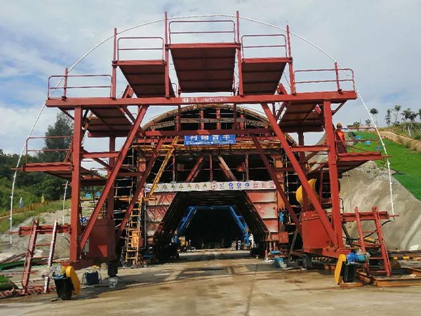
Steel formwork trolley structure
The steel formwork trolley structure is generally divided into the car body, formwork, hydraulic or screw support and disassembly system, which is manufactured in the factory and shipped to the site for assembly.
1. Trolley body
The trolley body adopts a truss structure, the longitudinal beams are made of 40C channel steel, 2 upper and lower sides respectively; the columns are made of HK450 steel, with a spacing of 1 per 3m, and a “meter” brace is set between the columns; the beam is 56C For the I-beam, the spacing is 1 per 1.5m; the other auxiliary components adopt HKl60c steel, and the above structure can better meet the requirements of rigidity and stability.
2. Template and assembly
Due to the large cross-section of the highway tunnel, practice has proved that the rigidity of the steel plate is less than 6mm, and it is prone to deformation after a period of use. In view of this, the template should be made of cold-rolled steel plate with a thickness of 8mm or a width of 10mm and a width of 150cm. When the formwork is processed, the rolling radius should be 5cm larger than the design clearance section radius of the tunnel to offset the construction error; the bottom end of the formwork should be 5-10cm lower than the top surface of the side trench of the tunnel to ensure that the joint between the second lining and the low side wall is not exposed. After the on-site assembly is completed and checked and corrected, the joints of the template plates are welded and the welds are smoothed. After the template is assembled, three blocks (one arch and one left and right wall) are formed. The large template can effectively suppress warping deformation.
3. Screw support and removal system
Screw support and disassembly system, the diameter of the rod body is 90mm, the longitudinal spacing is 150cm (the same as the width of the plate), and the two ends of the trolley are laterally adjusted on each side of the screw.
4. Work window setting
The size of the working window is 50×50cm, and there are 19 rows in 5 rows, that is, there are 3 in a row at the top of the dome, which are arranged alternately with 3 capping holes. There is a row on both sides above the arch line, each row has 4, the height should be about 20cm higher than the position of the embedded lighting cable pipe and junction box, so as to check and correct the position of the embedded parts during the concrete pouring process. There are 1 row of windows on the side walls on both sides, 4 in each row, and the appropriate height is 3.0m from the bottom of the formwork.
5. Determine the length of the trolley
The actual length of the trolley is preferably 1210cm, the effective length is 1200cm, and the overlap length between each ring is 10cm. Practice has proved that it is applicable when the line radius is greater than or equal to 500m, and the chord-vector difference can be offset by the screw adjustment. Too short trolley length will cause too many ring joints in the lining, which will affect the appearance of concrete and the progress. The lap length between the trolley formwork and the concrete surface of the upper ring is preferably 10-15cm. If the lap length is too small, the concrete at the lap joint of the upper ring will be easily cracked; if it is too large, the lap joint will not be easy to stick closely. Causes slurry leakage at the annular joint.
Commissioning after assembly of trolley
The trolley car body truss, local deformation of the formwork, and processing size deviation are the main reasons for the appearance quality problems of the lining such as staggered lining. After the trolley is assembled, the debugging is very important to the appearance quality of the secondary lining concrete. The following aspects should be paid attention to during the debugging:
a. After the on-site assembly of the lining trolley is completed, it must travel 3-5 times on the track, then tighten the bolts again, and strengthen welding on some of the connecting parts to improve its integrity.
b. Check whether the size of the trolley template is accurate, and the relative deviation of the structural size at both ends should not be greater than 3mm, otherwise it needs to be refurbished.
c. Use a polishing machine to thoroughly polish the surface of the steel template before lining, remove rust spots, and apply oil to prevent rust.
d. Every time 500-800m of lining is constructed, the trolley should be fully checked once, and the check is generally carried out in the tunnel with broadband.
Trolley in place
1. Track layout
The track should be steel rails above P38, wooden sleepers should be used for short sleepers, and rail pads should be used between the steel rails and short sleepers, and the track should be placed on the paved concrete floor to ensure the stability of the trolley. The track centerline coincides with the tunnel centerline as much as possible, and the deviation should be controlled within ±1cm.
2. Accurate positioning of the trolley
Trolley positioning adopts five-point positioning method, that is, a plane coordinate system is established with the center of the lining circle as the origin, and the center point of the arch template, the two hinge points of the arch template and the wall template, and the foot points of the two wall templates are controlled. The precise console car is in place. After the trolley travels to the position of the standing mold, first use the vertical screw to adjust its elevation, and then use the horizontal and lateral screws to adjust its plane position, so that the centerline of the template coincides with the centerline of the tunnel, and use the five-point positioning method to retest the platform For the cross section at both ends of the car template, pull the wire to check whether the middle template is warped or twisted until it is accurate.
In the construction of the curve section, the change in the overlap length between the left and right sides caused by the difference between the inner and outer arc lengths should also be considered, and the arc should be as smooth as possible during the adjustment process.
In order to prevent the trolley from floating during the concrete pouring process (usually up to 15mm), three 30t jacks are used to add support to the arch at the front end of the trolley to prevent the trolley from floating and causing the arch to be staggered.
Key Process Control of Molded Concrete

1. Raw material and concrete quality control
(1) Raw materials
The raw materials are used after passing the inspection, especially the floor materials and special materials. The crushed stone should be counter-attack crushed stone. The size of the screen hole should be strictly controlled during the production of crushed stone to ensure the shape and gradation of the crushed stone.
(2) Concrete slump control
The concrete slump is generally 14-17cm. According to the different pouring parts, the concrete slump of the wall should be small, and the arch should be larger. In the case of ensuring the pumpability of concrete, it is advisable to reduce the slump of concrete as much as possible, and improve the workability and water retention of concrete to avoid bleeding of concrete.
(3) Selection of admixture (material)
Adding an appropriate amount of high-efficiency retarding type water-reducing agent can improve the workability of concrete and increase its fluidity; adding fly ash to lining concrete is beneficial to improve the workability, water retention and compactness of concrete.
2. Concrete pouring
(1) Perfusion sequence
The concrete is poured in layers and alternately and symmetrically on the left and right sides, and the thickness of each layer is not more than lm. The height difference on both sides is controlled within 50cm . The pouring process should be continuous to avoid “cold joints” caused by stoppages. If the intermittent time exceeds 1.5h, it will be treated as construction joints.
(2) Bilateral symmetrical perfusion replacement time control
Two indicators of concrete pouring time and pouring height are used for dual control. That is, when the height of single-sided concrete pouring reaches 1m, the pipe must be replaced; the intermittent time of single-sided concrete pouring does not exceed the initial setting time of concrete. The construction of Meijianlin Tunnel stipulates that every When the side continuous perfusion time reaches 70min, the tube must be replaced.
(3) Measures to ensure the continuity of concrete pouring
a. Reasonably configure mechanical equipment and reserve sufficient wearing parts to ensure that the equipment is useful and well prepared; strengthen on-site training of mechanical equipment operators and equipment maintenance.
b. Establish an equipment inspection system before the lining operation, and the equipment fails or does not match the capacity and does not open.
c. For lining sections with a large amount of work, two sets of equipment can be used to work on the left and right sides at the same time, but the concrete pouring speed should be appropriately slowed to avoid the trolley from floating.
3. Concrete tamping
The full-time tamping hand is fixed and positioned with a plug-in vibrator to ensure the compactness of the concrete; below the arching line, it is supplemented with wooden hammer mould external percussion and tamping shovel to insert and tamping to suppress air bubbles on the concrete surface. It is strictly prohibited to drag the concrete with a vibrating rod during the pouring process.
4. Lining concrete capping
The roofing adopts the top mold center to seal the aluminum connecting pipe, and gradually pressure injects the concrete to seal the roof. When there is slurry overflow from the observation hole on the stop plate, it means that the capping is completed.
5. Demolition
According to the construction specifications, the strength achieved by the final test piece of the capped concrete on site is used to control, and the mold is removed when the strength of the molded lining concrete is not less than 2.5MPa.
6. Repair of concrete surface defects
After demoulding, if defects are found, they shall be dealt with in time after approval by the supervision engineer.
a. Air bubbles: After mixing white cement and ordinary cement according to the ratio determined by the lining surface color comparison test, they are partially filled and smoothed.
b. Circular seam treatment: draw lines with a radian ruler, cut the seams with a cutting machine, the seam depth is about 2cm, and the irregularities are locally repaired or polished by a grinder, then modified with high-grade cement mortar, and smoothed with a steel trowel. The seams are round and neat.
c. Inconsistent surface color: Use sandpaper to wipe several times.
d. Treatment of the periphery of the reserved cavern: The periphery of the reserved cavern should also be cleaned first, and then sprayed with water to moisten it. Use high-grade mortar with the same color as the molded lining to smooth and calender.
7. Several process details in lining concrete pouring operation

(1) Concrete delivery pipeline layout
The joint pipe clamp should be connected firmly to avoid bursting off, and the pipeline shall be raised above the ground with square wood, and the pipe clamp shall not directly contact the trolley components when passing through the trolley. A hose is set at the end of the concrete delivery pipeline, and the vertical distance from the hose nozzle to the pouring surface is controlled within 1.5m to avoid segregation of the concrete.
(2) Measures to ensure the thickness of the reinforced protective layer
Due to the use of pumped concrete, the pouring speed is faster, and the deformation of the steel bar is more significant, which is likely to cause the steel protection layer of the arch to be reduced, and even the bars are exposed. Therefore, it is necessary to ensure that the arch concrete pad has sufficient strength and pay attention to the concrete pouring speed during the pouring process.
(3) Control of air bubbles on the concrete surface of the reverse arc section of the side wall
In order to control the air bubbles on the concrete surface during the construction of the reverse arc, the following three measures are mainly adopted:
a. Add high-efficiency retarding water reducer (generally 1% of cement weight) and fly ash (generally about 20% of cement weight) to improve concrete performance;
b. Control the slump of concrete (usually 14cm);
c. The proper tamping method and comprehensive application can reduce the bubbles in the anti-arc section and effectively improve the surface quality of the lining concrete.
(4) Measures to overcome the dislocation of concrete joints
Staggered concrete joints is one of the common problems in the appearance quality of molded linings, but it can be overcome by taking some specific measures. The deviation of wall flatness can be controlled within 3mm, far less than the allowable value of 20mm.
a. Measures to overcome misalignment at annular joints
The following measures should be taken to overcome the misalignment of the circular joints: First, before the trolley is in place, thoroughly clean up the concrete overlapping part and the surface of the trolley overlapping part, so that the trolley and the concrete surface are as close as possible; The second is to strengthen the support of the trolley. All supports should be supported in place to ensure the overall force of the trolley. Screw supports should be added to the side walls at both ends of the trolley. The third is to add vertical supports at the top of the front end of the trolley. (Using three 30t jacks) to prevent the floating of the trolley from causing misalignment of the arch; the fourth is to slow down the concrete pouring speed of the 0-3m high part of the side wall (usually about 4 hours) and strictly control the concrete slump ( Generally 14cm); Fifth, check and eliminate the cross-section error at both ends of the trolley in time; Sixth, the center line and elevation must be controlled accurately; Seventh, ensure that the overlap length between the trolley template and the concrete of the upper ring is 10-15cm.
b. Measures to overcome the misalignment of the joints of the trolley template plates
Weld the joints of the template plates and smooth the welds to form three large templates (one arch and one on the left and right side walls) to suppress local warpage and deformation of the template during use, and avoid wrong joints of the plates station.
c. Wrong platform at the operating window of the console car
Before closing the operation window, the residual concrete slurry on the window frame must be cleaned up, wiped with a damp cloth, and then tighten the compression card, and the closing fulcrum should be plugged tightly with a wedge-shaped wood to prevent the window frame from being closed tightly and the concrete surface of the window Uneven.
(5) Measures to overcome slurry leakage
a. Treatment measures for slurry leakage at annular joints: First, the baffle should be thick, and can be made of 5cm thick wood. The wooden mold is installed radially to adapt to the irregularity of the end size. Drill holes at the ribs of the template plate at the end of the trolley Fix with channel steel and bolts; second, the lap length between the trolley steel formwork and the concrete surface of the upper ring should be 10-15cm, and should not be too large, otherwise the lap joints will not be easy to stick closely and cause slurry leakage; the third is lap joint Paste sponge strips to stop the grout on the concrete surface.
b. Treatment measures for the concrete joint mortar on the top surface of the low side wall: one is to seal the gap between the top surface of the low side wall and the bottom edge of the trolley formwork with trapezoidal wood; the other is to pump the same grade mortar and mortar before opening The appropriate amount is 2cm flat on the low side wall, which can not only ensure the connection between the low side wall and the arch wall concrete, but also prevent the leakage of the formwork from causing the concrete to flood or expose the aggregate.
(6) Measures to overcome the inconsistency of concrete surface patterns and colors
a. Eliminate cold joints and reduce unnecessary construction joints. As mentioned above, the concrete should be layered and poured alternately and symmetrically on the left and right sides, and the pouring process should be continuous to avoid “cold joints” caused by pauses, and control the replacement time of symmetrical pouring on both sides to avoid unnecessary construction joints.
b. Use a suitable release agent. After repeated comparison experiments, the mixture of engine oil and diesel oil is mixed in a ratio of 4:6 and used as a release agent, and the effect is better. The brush should be thin and even. After the first brush, the brush should not be dipped in oil and then brush it evenly. Cut the flow range of the concrete.
Construction method and technology of low side wall
Before lining the large formwork trolley, a shaped steel formwork must be used to construct the low side wall first. There are generally two options for the construction height of low side walls: that is, slightly higher or lower than the bottom of the lining trolley formwork. The first solution requires high elevation and straightness of the low side wall, otherwise it is difficult for the console car template to be accurately positioned or the stubble joint is prone to leakage, but it is easy to demold. The second solution is easy to realize the accurate positioning of the trolley. The disadvantage is that the height difference is kept small, which makes it difficult to demold. The edges and corners of the low side wall are often broken, the height difference is too large, the gap is not easy to seal, and the slurry is easy to leak when pouring concrete.
After comparative analysis and combined with the construction experience of multiple highway tunnels, we choose the second option. The top surface of the low side wall is about 8cm lower than the bottom of the lining trolley formwork. This part is sealed with trapezoidal wood before the concrete is poured. Paste to prevent leakage.

