Lining lining trolley design plan description
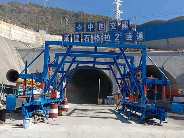
Tunnel lining trolley structure
Lining lining trolley oil template assembly, bench assembly, gantry assembly, template vertical lifting system and lateral expansion system, translation system, walking system, hydraulic system, electrical control system, etc.
1. Template assembly
The formwork is an important part of the formwork lining trolley. Its structure, manufacturing process and strength are directly related to the quality of the tunnel lining. The template designed and manufactured by our company is composed of top mold and side mold. Considering that the steel has a flexible deformation after being stressed, according to experience, the radius of the section is increased by 5cm when designing the template. The top mold and the side molds are connected by bolts. In order to prevent the wrong stage, the template is bolted and then the positioning pins are added.
A hinge mechanism is used between the side mold and the top mold, which is used for the vertical mold and the mold retraction. 9.2m long formwork Lining trolley, the formwork is divided into 5 pieces, the middle 4 pieces each have a length of 2m, the end is 1m, and a 0.2m flexible overlapping block grows. The formwork consists of panels, flanges, reinforced angles, and ribbed plates. The thickness of the formwork panel is 10mm, and the thickness of the flanges at both ends is 12mm. Considering the welding stress of the lining trolley during the manufacturing and storage process, the flange is retracted. A few 10# channel steel is added between the two flanges for support.
100*63*10 angle steel for formwork strengthening angle is arranged along the width of formwork, and the spacing is 326mm. There are working windows arranged in the shape of a product on the template. The clear space distance is about 1.5 meters, and the size is 500*500. A steel plate is added around the window to prevent slurry leakage. The connection is bolted to prevent loosening during the pounding process. Wrong platform. The side mold and the side mold are connected with the portal frame through the side mold through beam and the lead screw.
2. Walking system
The walking system is composed of active and passive parts, a total of 4 sets of devices, which are respectively installed at the lower ends of the gantry columns at both ends of the lining trolley frame. To make the driving wheel drive the whole machine and the passive wheel to follow. There are brake devices at both ends to ensure that the machine can park safely on the slope. The walking console is installed on the lower longitudinal beam for easy operation.
3. Bench assembly
The bench mainly bears the weight of the upper concrete and formwork during pouring. The force it bears is transmitted to the gantry through the upper stringer below.
4. Door frame assembly
The gantry is composed of upper and lower longitudinal beams, gantry legs, diagonal rods, support rods, etc. All parts are connected by bolts, the two ends of the gantry are supported on the walking wheel frame, and the ground support screw is installed under the middle gantry When lining, the concrete load is transferred to the portal frame through the formwork, and then to the ground through the walking wheel and the ground screw. When the lining trolley is walking, the ground screw is retracted. The 9-meter lining trolley is composed of 6 portal frames.
5. Translation mechanism
The translation mechanism is installed on the gantry at both ends of the lining lining trolley. When the tunnel excavation is off-center, the translation mechanism of the lining lining trolley is adjusted to achieve the adjustment and meet the design and construction requirements.
6. Hydraulic system
The hydraulic system is composed of hydraulic pump, motor, manual directional valve, hydraulic cylinder, hydraulic lock, oil tank and pipeline. The manual directional valve controls the vertical lifting of the template, the expansion and contraction of the side mold, and the left and right movement of the translation cylinder. The hydraulic pump station is installed in the middle of the upper working platform of the first gantry, which is easy to operate.

The working principle of the lining trolley
Vertical mould: After the lining trolley is moved into place by the walking system, the brake system is locked; the height of the lining trolley is raised into position by lifting the hydraulic cylinder. If the center of the lining trolley and the center of the tunnel deviate, the template is adjusted by adjusting the translation mechanism In the middle, tighten the ground screw and the track under the mast; adjust the lateral oil cylinder and push the side mold into place to prevent the oil cylinder from leaking and cause the template to retract. Tighten the lateral screw and the ground screw.
Retract: After the concrete solidifies, first loosen the screw from top to bottom. Close the side mold, lift the cylinder down. The mold closing is completed.
Basic technical parameters and technical performance of lining trolley
Maximum length of template: L=9200mm
Maximum throughput (height x width): 5000mm*4500mm
Lining trolley gauge: B=8000mm
Walking speed: 8m/min
Climbing ability: 3%
Lining thickness: max. 500mm
Power supply: 3/1=380v/220V
Total power: 50.5Kw
Walking motor: 7.5kw*2=15kw
Oil pump motor: 5.5kw
Hydraulic system pressure: p=16MPaPmax=20MPa
Technical parameters of cylinder
Jacking cylinder: D200*100*S300
Lateral cylinder: D100*d63*S200
Horizontal adjustment cylinder: D100*d63*S200

The implementation of relevant standards and technical specifications
1. Specification for acceptance of overall dimensions of formwork lining trolley
| Serial number | Project | Standard (error) |
| 1 | Contour radius | ±3mm |
| 2 | Template plane | 2mm/2m |
| 3 | Template is wrong | ≤1mm/m |
| 4 | Formwork seam gap | ≤1mm |
| 5 | Surface roughness | Anti-rust repair/no rust |
| 6 | The longitudinal straightness error of the outer surface of the template trolley | ≤1mm/2m
≤5mm/10m ≤6mm/12m |
| 7 | The working window surface is consistent with the template surface arc, staggered, gap error | ≤1mm |
| 8 | Contour error of front and rear of template trolley | ≤1mm |
2. Tolerances and inspection methods of structural dimensions
| Serial number | Project | Side wall | Camber | Tunnel bottom | Testing method |
| 1 | Flat position | +10mm | / | / | Ruler |
| 2 | Verticality | ±2%。 | / | / | Ruler |
| 3 | Elevation | / | ±30mm
0 |
0
-10mm |
Leveling |
| 4 | Structural plane
Flatness |
10mm | 10mm | / | 2m by ruler or profile meter side measurement |
3. Allowable assembly deviation of the trolley
| Serial number | Project | Standard |
| 1 | Trolley net span | ±4mm |
| 2 | Gap between the two ends of the trolley | ±7mm |
| 3 | The corner line formed by the center line of the trolley column | ±10mm |
| 4 | Requirements for the coaxiality of the vertical mast and the vertical cylinder | 1/1000 |
| 5 | Same-surface deviation of longitudinally arranged lateral cylinders to jack | |
| 6 | The top surface when the vertical cylinder shrinks to the lowest position should be in the same plane | ±4mm |

